
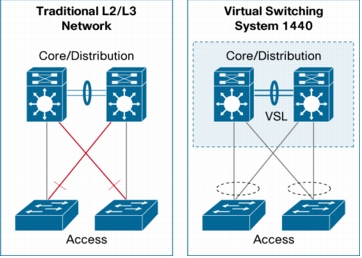
VSS (Virtual Switch System) est une technologie de virtualisation de switch Cisco.
Le switch viruel 1440 (VSS1440) est composé de 2 switch Cisco Catalyst 6500 interconnectés par un lien VSL (Virtual Switch Link)
Une carte Supervisor 720-10GE est utilisé par châssis 6500.
Le lien VSS est assuré par les interfaces 10To de la carte Sup.
La distance entre 2 membres du VSS varie entre 15m et 80km, en fonction des modules 10To utilisés (cuivre ou optique):
- X2-10GB-CX4: 15m
- X2-10GB-LX4: 300m
- X2-10GB-SR: 26m (FDDI grade MMF), 300M with OM3 MMF)
- X2-10GB-LR: 10km
- X2-10GB-ER: 40km
- X2-10GB-LRM: 220m over MMF
- X2-10GB-ZR: 80km
Le lien VSL est un port channel pouvant être composé de 2 à 8 liens,
Le lien VSL assure la synchronisation des 2 membres, il transporte les informations de contrôle et les données.
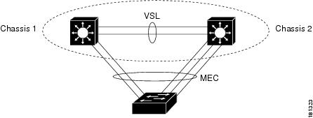
un châssis obtient le rôle « Active », l’autre le rôle « Standby ».
L’architecture VSS permet d’assurer les fonctions suivantes :
- stateful switchover (SSO)
- nonstop forwarding (NSF).
- lien MEC – Multichassis EtherChannel
User Actions :
6K500-VSS#show switch virtual
Switch mode                  : Virtual Switch
Virtual switch domain number : 110
Local switch number          : 1
Local switch operational role: Virtual Switch Active
Peer switch number           : 2
Peer switch operational role : Virtual Switch Standby
6K500-VSS#show switch virtual link
VSL Status : UP
VSL Uptime : 3 years, 5 weeks, 4 days, 22 hours, 53 minutes
VSL SCP Ping : Pass
VSL ICC Ping : Pass
VSL Control Link : Te1/5/5
6K500-VSS#show switch virtual role

Switch  Switch Status  Preempt    Priority  Role     Session ID
        Number         Oper(Conf) Oper(Conf)         Local  Remote
------------------------------------------------------------------
LOCAL    1     UP      FALSE(N )   110(110)  ACTIVE   0      0
REMOTE   2     UP      FALSE(N )   100(100)  STANDBY  6444   6146

In dual-active recovery mode: No
show switch virtual redundancy
ou
show redundancy
6K500-VSS#show redundancy
Redundant System Information :
------------------------------
       Available system uptime = 3 years, 5 weeks, 4 days, 22 hours, 55 minutes
Switchovers system experienced = 0
              Standby failures = 0
        Last switchover reason = none

                 Hardware Mode = Duplex
    Configured Redundancy Mode = sso
     Operating Redundancy Mode = sso
              Maintenance Mode = Disabled
                Communications = Up

Current Processor Information :
-------------------------------
               Active Location = slot 1/5
        Current Software state = ACTIVE
       Uptime in current state = 3 years, 5 weeks, 4 days, 22 hours, 54 minutes
                 Image Version = Cisco IOS Software, s72033_rp Software (s72033_rp-ADVIPSERVICESK9_WAN-M), Version 12.2(33)SXI2a, RELEASE SOFTWARE (fc2)
Technical Support: http://www.cisco.com/techsupport
Copyright (c) 1986-2009 by Cisco Systems, Inc.
Compiled Wed 02-Sep-09 00:59 by prod_rel_team
                          BOOT = sup-bootdisk:s72033-advipservicesk9_wan-mz.122-33.SXI2a.bin,1;
        Configuration register = 0x2102

Peer Processor Information :
----------------------------
              Standby Location = slot 2/5
        Current Software state = STANDBY HOT
       Uptime in current state = 3 years, 5 weeks, 4 days, 22 hours, 50 minutes
                 Image Version = Cisco IOS Software, s72033_rp Software (s72033_rp-ADVIPSERVICESK9_WAN-M), Version 12.2(33)SXI2a, RELEASE SOFTWARE (fc2)
Technical Support: http://www.cisco.com/techsupport
Copyright (c) 1986-2009 by Cisco Systems, Inc.
Compiled Wed 02-Sep-09 00:59 by prod_rel_team
                          BOOT = sup-bootdisk:s72033-advipservicesk9_wan-mz.122-33.SXI2a.bin,1;
        Configuration register = 0x2102